
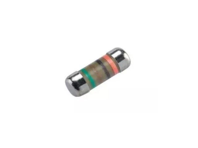
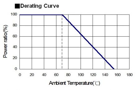
High voltage MELF metal film precision resistor, ready for the size of 0204/0207. Tight tolerance of 0.1%, 25/50ppm. 340K~3.4Mohm. Max Overload upto 2000V. The MELF is cylindrical in shape and with metal electrode Leadless face resistor. Land pattern sizes are the same as SMD chip resistors. High quality of MELF resistors offer excellent electrical and Environmental Stability, exceptional stability demonstrated over life, biased humidity, and short time overload testing.
AEC-Q200 Qualified
Thin film technology
High voltage application
Sn termination on Ni barrier layer
Tight tolerance down to ±0.1%
High power rating up to 1 Watts
SMD enabled structure
Lead-free and RoHS compliant
Sulfur resistance unaffected by sulfur environments
Industrial
Telecommunication
Medical Equipment
Measurement/Testing Equipment

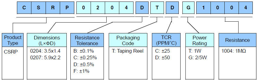
Part Number:CSRP0204FTDG1004
| Item Type | Power Rating at 70°C | Operating Temp. Range | Max. Operating Voltage | Max. Overload Voltage | Resistance Range | TCR (PPM/°C) | |||
|---|---|---|---|---|---|---|---|---|---|
| ±0.1% (E24,E96) | ±0.25% (E24,E96) | ±0.5% (E24,E96) | ±1% (E24,E96) | ||||||
| 0204 | 2/5W | -55 ~ +155°C | 700V | 1400V | 100KΩ-1MΩ | 100KΩ-3.4MΩ | ±25 | ||
| 100KΩ-1MΩ | 100KΩ-3.4MΩ | 100KΩ-10MΩ | ±50 | ||||||
| 0207 | 1W | -55 ~ +155°C | 1200V | 2400V | 100KΩ-1MΩ | 100KΩ-3.4MΩ | ±25 | ||
| 100KΩ-1MΩ | 100KΩ-3.4MΩ | 100KΩ-10MΩ | ±50 | ||||||
Operating Voltage=√(P*R) or Max. operating voltage listed above, whichever is lower.
Overload Voltage=2.5*√(P*R) or Max. overload voltage listed above, whichever is lower.
RCWV(Rated Continuous Working Voltage)=√(P*R) or Max. Operating Voltage whichever is lower.
☑ Viking is capable of manufacturing the optional spec based on customer's requirement.
The single impulse graph is the result of 50 impulses of rectangular shape applied at one-minute intervals. The limit of acceptance was a shift in resistance of less than 1% from the initial value. The power applied was subject to the restrictions of the maximum permissible impulse voltage graph shown.
The continuous load graph was obtained by applying repetitive rectangular pulses where the pulse period was adjusted so that the average power dissipated in the resistor was equal to its rated power at 70°C. Again the limit of acceptance was a shift in resistance of less than 1% from the initial value.
Resistors are tested in accordance with IEC 60115-1 using both 1.2/50us and 10/700us pulse shapes. The limit of acceptance is a shift in resistance of less than 0.5% from the initial value.