
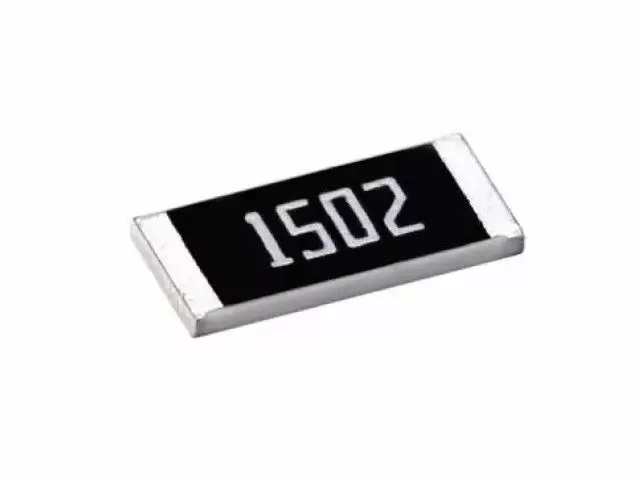

Surge/Pulse protection is essential for all circuit designs. SWR series , size from 0402-2512, Tolerance 5%~10%, 1ohm~20Mohm. More circuit design is becoming more critical. Surge/Pulse protection is essential for all circuit designs. Viking’s SWR series, untrimmed on resistance layer remains the superior pulse and ESD withstanding resistor is suitable for protection of electronic circuits against extreme pulses and surges. Resistors withstand the pulse or surge are required in the circuit where large current is instantaneously applied or ESD is applied. Surge means overload like ESD or high voltage with short duration. Anti-Surge resistors can prevent the damage from large power instantaneously applied.
High power rating.
Excellent surge withstanding & pulse withstanding performance.
Improved working voltage ratings.
Standard package sizes of 0402~2512.
AEC-Q200 Compliance.
MSL: Level 1.
Metering (Testing/Measurement)
Medical Devices
Automotive
Power supply
Charger
Inverter
LCD Video Monitors
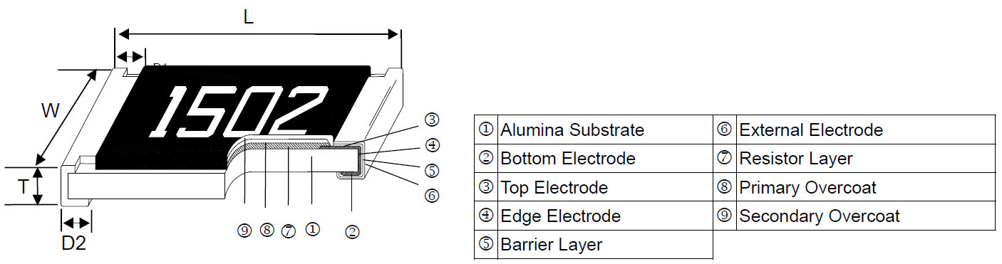
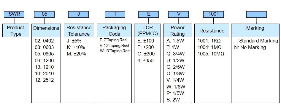
| Item Type | Power Rating at 70°C | Operating Temp. Range | Max. Operating Voltage | Max. Overload Voltage | Resistance Range | TCR (PPM/°C) | ||
|---|---|---|---|---|---|---|---|---|
| ±5% (E24) | ±10% (E24) | ±20% (E24) | ||||||
| SWR02 (0402) | 1/5W | -55 ~ +155°C | 50V | 100V | 1Ω -20Ω | ±300 | ||
| 22Ω - 1MΩ | ±100 | |||||||
| SWR03 (0603) | 1/8W | -55 ~ +155°C | 50V | 100V | 1Ω - 270Ω | ±200 | ||
| 300Ω - 1MΩ | ±100 | |||||||
| SWR05 (0805) | 1/4W | -55 ~ +155°C | 150V | 300V | 1Ω - 270Ω | ±200 | ||
| 300Ω - 20MΩ | ±100 | |||||||
| SWR06 (1206) | 1/3W | -55 ~ +155°C | 200V | 400V | 1Ω - 20Ω | ±200 | ||
| 22Ω - 20MΩ | ±100 | |||||||
| SWR13 (1210) | 1/2W | -55 ~ +155°C | 200V | 400V | 1Ω - 20Ω | ±200 | ||
| 22Ω - 20MΩ | ±100 | |||||||
| SWR10 (2010) | 3/4W | -55 ~ +155°C | 400V | 800V | 1Ω - 20Ω | ±200 | ||
| 22Ω - 20MΩ | ±100 | |||||||
| SWR12 (2512) | 1.5W | -55 ~ +155°C | 500V | 1000V | 1Ω - 20Ω | ±200 | ||
| 22Ω - 20MΩ | ±100 | |||||||
Operating Voltage=√(P*R) or Max. Operating Voltage listed above, whichever is lower.
Overload Voltage=2.5*√(P*R) or Max. Overload Voltage listed above, whichever is lower.
The power rating depends on the maximum temperature of the resistive element. Due to the power dissipation of the resistor, the temperature of the resistive element will rise depending on the condition of heat dissipation from PCB. The maximum power rating in application only applies if the temperature of the resistive element is not exceed 155 ° C.
☑ Viking is capable of manufacturing the optional spec based on customer's requirement.
The single impulse graph is the result of 50 impulses of rectangular shape applied at one-minute intervals. The limit of acceptance was a shift in resistance of less than 1% from the initial value. The power applied was subject to the restrictions of the maximum permissible impulse voltage graph shown.
The continuous load graph was obtained by applying repetitive rectangular pulses where the pulse period was adjusted so that the average power dissipated in the resistor was equal to its rated power at 70°C. Again the limit of acceptance was a shift in resistance of less than 1% from the initial value.
Resistors are tested in accordance with IEC 60115-1 using both 1.2/50us and 10/700 pulse shapes. The limit of acceptance is a shift in resistance of less than 1% from the initial value.